ESA Tracking Sites Directory
In order to perform precise orbit determination, highly accurate antennae positions for the ESTRACK Ground Stations are required. A dedicated directory providing the information about the antennae positions in a global coordinate system is the ESA Tracking Site Directory (ESA TSD) maintained by ESOC’s Navigation Support Office.
Besides the provision of the antennae positions, the local geodetic networks on the various sites are documented in the ESA TSD. In case of installation of new antennae or constructional alterations, this will enable the determination of antennae positions by use of the existing geodetic network. The ESA TSD thus consists of two main components per tracking site:
-
Antenna information with positions of the geometric Antenna Reference Points (for definition see below)
-
Local geodetic network with coordinates and documentation of network and single points
In 1992 the first version of the ESA Tracking Site Directory (ESA TSD 1) was issued: The geocentric coordinates at selected ESA sites were determined with about 5 - 10 cm accuracy by means of at that time state-of-the-art GPS baseline measurements. During the following decade, GPS technology as well as GPS satellite coverage and the achievable accuracy of GPS measurements had significantly improved. In addition, new ESA tracking sites and tracking sites used by ESA were established until 2002, and new antennae were installed at various other tracking sites. Therefore, in 2002, a major update of the ESA TSD 1 was strongly recommended.
Objective of the 2002 ESA Tracking Site Directory update was to determine geocentric coordinates of the Antennae Reference Points (ARP, crossing point of an antenna’s azimuth axis with the antenna’s elevation axis, for the precise definition see below) of ESA ground sites tracking antennae in the global reference system: International Terrestrial Reference Frame 2000 (ITRF 2000) (Ref. [3]). For this purpose, geodetic surveys were conducted on the various tracking sites from 2002 - 2005. The work was generally organized in the following manner: Geocentric ITRF 2000 reference coordinates for a marker on each site were provided by the ESOC Navigation Support Office. The ARPs were tied to these ITRF 2000 markers by local surveys. This strategy was chosen to perform the work with almost equal standards for all sites and to set up a modern site directory, the ESA TSD 2, which can easily be maintained and updated in case of changes.
In 2012 a further update of the ESA TSD 2 was made with respect to two major targets:
-
Inclusion of ESA’s new Deep Space Antenna (DSA-3) in Malargüe, Mendoza, Argentina.
-
Conversion of the whole ESA TSD 2 from the ITRF 2000 (Ref. [3]) to the new ITRF 2008 ( http://itrf.ensg.ign.fr/ITRF_solutions/2008/ITRF2008.php )
Also this work was done by ISS & TUD/PSGD.
The tracking sites now included in the ESA TSD 2 are (2002 – 2005 & 2012), Figure 1: Kourou/French Guyana, Kiruna/Sweden, Malindi/Kenya, Maspalomas/Canary Islands/Spain, New Norcia/Australia, Perth/Australia, Redu/Belgium, Svalbard/Norway, Villafranca/Spain, Cebreros/Spain, Malargüe/ Argentina. More antennae may be included in future.
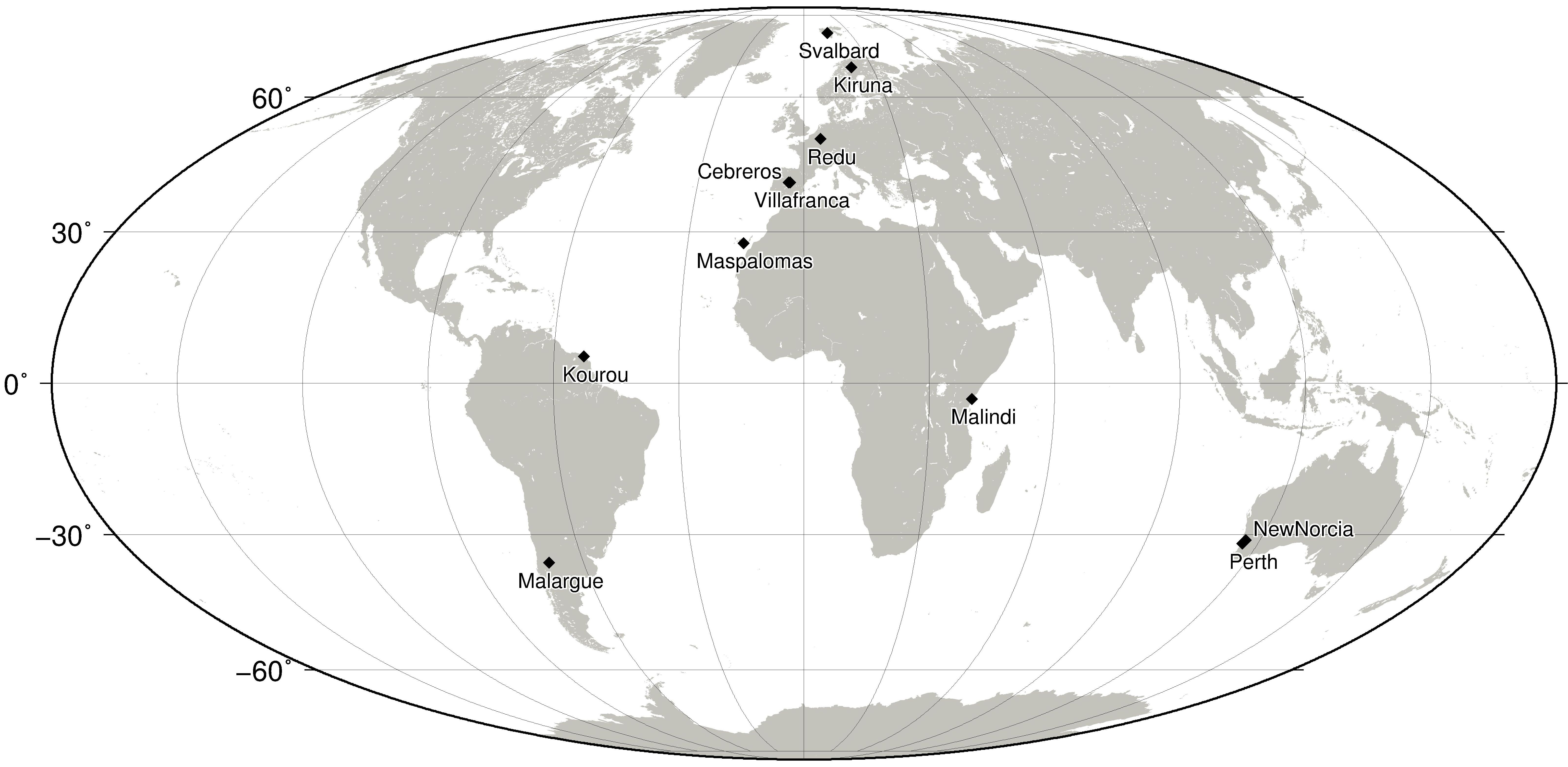
Figure 1: Sites included in the ESA Tracking Site Directory Version 2 in 2012
The following chapters provide an overview of the ESA TSD 2 and intended future upgrades. For further details and information the interested reader is referred to Refs [1] & [2].
Conception of the geodetic measurements
At each tracking site, one reference point is available whose geocentric coordinates are precisely known within the ITRF (before the 2012 upgrade in ITRF 2000, thereafter in ITRF 2008). This reference point was/is occupied with a high precision geodetic GPS receiver, determining permanently the accurate ITRF position, as part of the Navigation Support Office’s activities within the International GNSS Service (IGS) ( http://igscb.jpl.nasa.gov ). Main purpose of the local surveys was to tie the ARP positions of selected antennae to this ITRF reference point with high accuracy; anticipated were ARP positions with a horizontal accuracy of ± 3 mm and a height accuracy of ± 6 mm relative to this local ITRF reference point. The methodology to achieve this task splits into four parts:
-
ITRF Connection
-
Geodetic Network Measurements
-
Antenna Measurements
-
Transfer of Results to Reference Epoch
ITRF Connection
On most sites, a permanent IGS/GPS station is being operated by the Navigation Support Office for a long time, and the ITRF position and velocity are well known with sufficient accuracy form the routine processing for the IGS. On some sites, permanent GPS stations had to be newly established, like in Malargüe, or run only sufficiently long in parallel to the local surveys. The precise ITRF positions computed at the Navigation Support Office were then used as fixed points for the local measurements' evaluation and connection of all local points, in particular the ARPs, to the ITRF.
Geodetic Network Measurements
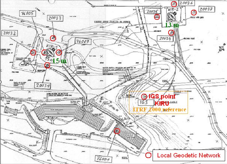
Figure 2: PCN Example: Kiruna
A Primary Control Network (PCN) of geodetic markers was established on each site to tie the ARPs to be measured to the ITRF reference point. This PCN served as basis for the actual as well as future surveys. The PCN points were monumented and documented properly. The ITRF reference point is part of the PCN as well. Were suitable, the local surveys were performed with differential static GPS or otherwise by conventional geodetic methods. For a proper ARP measurement, 4 – 6 of these geodetic markers must be arranged equally around one antenna. Figure 2 shows exemplarily the situation at the Kiruna site.
Antenna Measurements
From the PCN points surrounding one antenna, conventional geodetic measurements by tacheometer (electronic distance measurements, horizontal and vertical angle measurements) were performed to target points attached to the antenna building. The coordinates of these target points were then used to calculate the ARP position of that antenna. This procedure will be described in detail in the next Chapter.
Transfer of Results to Reference Epoch
The PCN and ARP coordinates at the mean epoch of local survey had to be transferred to the ITRF reference epoch (for ITRF 2000 this was the 01.01.1997, 0h UTC, for the ITRF 2008 this is the 01.01.2005, 0h UTC).
Determination of the antenna reference point
The ARP is defined as the crossing of the antenna's azimuth axis with the elevation axis. Normally the ARP is only a virtual but not physically existing point. Special geodetic observation methods were worked out as part of the ESA TSD 2 project to enable the precise measurement of the ARP location. Some types of antennae are equipped with a tilt mechanism. In these cases extended ARP definitions, related with additional measurements, were required, details below.
Targets attached to the antenna (e.g. self-adhering markers, but also clearly identifiable points on the antenna building, etc.) were measured from the PCN points by means of tacheometry. In addition, levelling measurements were performed to support the height determination in some cases. The following methods for survey and ARP calculation were applied, depending on antenna type:
-
Antenna Traverse Method (AT)
-
Indirect Method (IM)
-
AntennaBuildingMethod (AB)
The evaluation of these tacheometry data led to the ITRF positions of the target points attached to the antenna. The ITRF position of the ARP was finally derived from the target points coordinates, at local survey epoch.
Antenna Traverse Method (AT)
For the AT method, the ARP is plumbed down to the floor of the antenna tower, and a permanent marker is set on the floor vertically beneath the ARP in a proper way. In addition, the vertical measure between this marker and ARP is accurately surveyed. Two further points (four in Malargüe) on the floor are marked close to the entrance door of the antenna tower and surveyed relative to the marker vertically below the ARP. These works are done by the antenna manufacturer during the antenna construction.
The two markers (four markers in Malargüe) close to the entrance door (and, if possible, the marker vertically beneath the ARP as well) are then connected to the PCN within the local survey by means of levelling and tacheometry. Having determined these points' coordinates within the antenna network evaluation, the calculation of the ARP, based on the relative measures provided by the manufacturer, is straightforward. The ARP can then easily be determined with a rather low measurement effort and well within the requirements of the project.
The AT method was so far only applied to the New Norcia, Cebreros and Malargüe 35 m antennae.
Indirect Method (IM)
The IM method for ARP coordinates determination was worked out especially for the ESA TSD 2 project. The principle of the IM is to determine the ARP exclusively from geodetic measurements, i.e. without using additional information of questionable quality, like e.g. construction blueprints. Instead, the position of azimuth and elevation rotation axes in 3D space is calculated solely from the positions of markers attached to the turnable elevation housing of the antenna. Measurements are made under 4 – 6 different azimuth positions (depending on anticipated ARP horizontal accuracy), equally distributed around the azimuth circle, in constant elevation. The coordinates of the elevation housing markers thus obtained describe a horizontal circle, whose centre coordinates correspond to the horizontal position of the ARP. Analogously, measurements are made under 4 – 6 elevation positions, equally distributed between 0o – 90o degrees of elevation, in one or two constant azimuths (depending on anticipated ARP vertical accuracy). The centre of the resulting vertical circle corresponds to the vertical ARP position. The circles centre locations are determined from the elevation housing markers coordinates with dedicated circle fitting algorithms [2]. The method is based on tacheometry measurements only. Figure 3 tries to illustrate the IM principle: Top: ARP definition as crossing of azimuth with elevation axis. Middle and bottom: IM principle illustrated for the measurements in different azimuth positions under constant elevation, i.e. determination of the horizontal ARP position as centre of the horizontal circle (the arrows indicate the positions of the markers attached to the elevation housing). For further illustration see the sequence of antenna positions during the IM measurements in Cebreros (=> link to Cebreros PowerPoint).
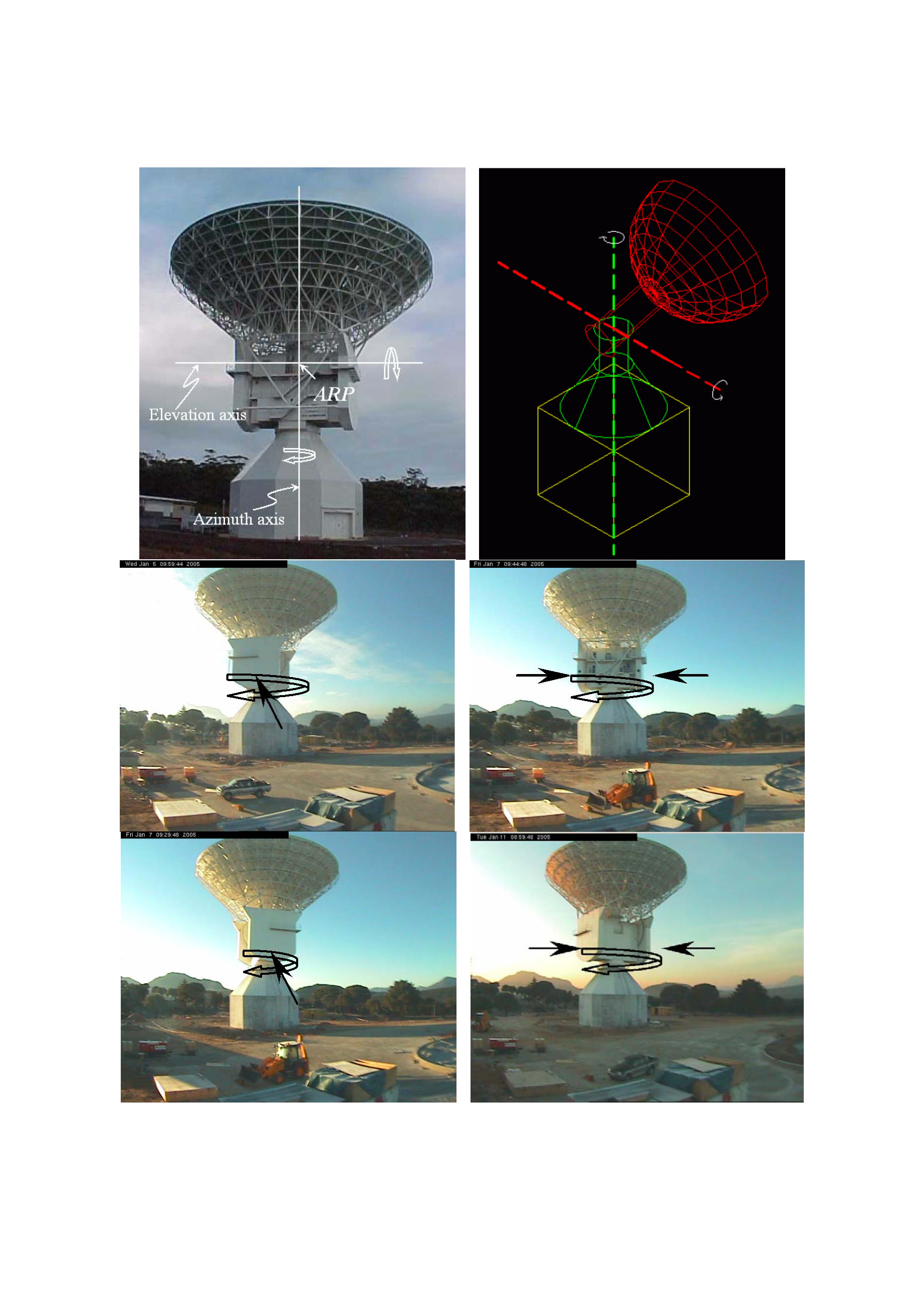
Figure 3: IM Method Principle
The measurement effort is rather high since the markers on the elevation housing have to be measured in a lot of antenna positions and the method requires moving the tacheometer between PCN points frequently. The determination of the ARP from the marker positions implies a lot of calculations. High accuracies, well within the requirements of the project, are achievable and no additional measures are necessary.
The IM method's capability and suitability was proved at the New Norcia tracking site by comparison with the AT results (agreement of 2 mm in vertical as well as in horizontal) and became then the major method of ARP determination throughout the project, since, apart from New Norcia, Cebreros and Malargüe, no AT measurements were available for the rest of the antennae involved.
iii) AntennaBuildingMethod (AM)
The principle of the AB method is to measure some points of the antenna building, which can be clearly identified on given blueprints. The blueprints must contain measures, which relate these points to the ARP of the antenna, thus allowing for the calculation of the ARP position. Additionally, an assumption has to be made that the ARP resides vertically above the geometric centre of the lower part of the antenna building (e.g. centre of a square, octagon, decagon, or circle) if only vertical measures to the ARP are given in the available blueprints (this is the usual case). Measurements were made by tacheometry, partly supported by levelling. This kind of methodology was mainly used in 1991/1992 for the establishment of the ESA TSD 1. Figure 4 tries to illustrate the AB method principle, where the Points 15001 – 004 were measured, and the ARP position with respect to these points is available from a blueprint.
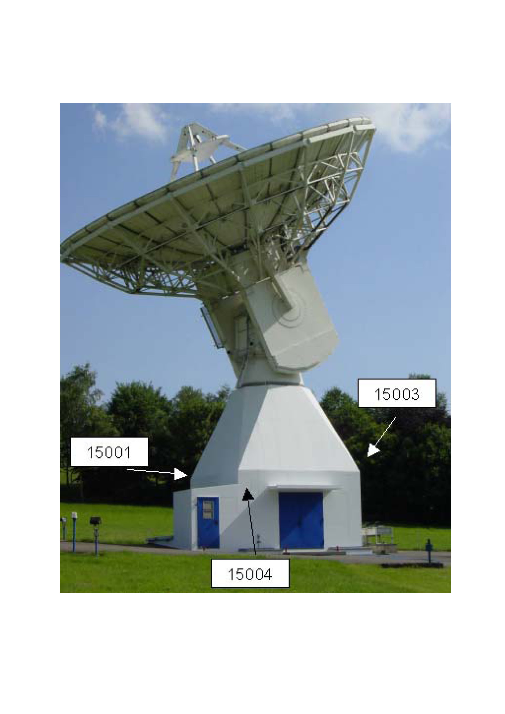
Figure 4: AB Method Principle
The ARP accuracy depends essentially on the accuracy of the measures given in the blueprint. For the ESA TSD 2, the AB method was not considered to be a suitable method of ARP determination with respect to required accuracy and to reliability of the result. It served only as a rough verification of the other methods.
Antennae with Tilt Mechanism
Some of the parabola antennae are equipped with a tilt mechanism in order to avoid rising of the elevation housing above 90o elevation with respect to the antenna building when tracking a satellite close to zenith. Figure 5 shows as example the 13 m Antenna in Kiruna. This antenna can be moved into a 7o tilt west or east, i.e. it can reside in two ARP positions, depending on the actual tilt. In such a case, two ARPs have to be determined with the IM method, one in each tilt position.
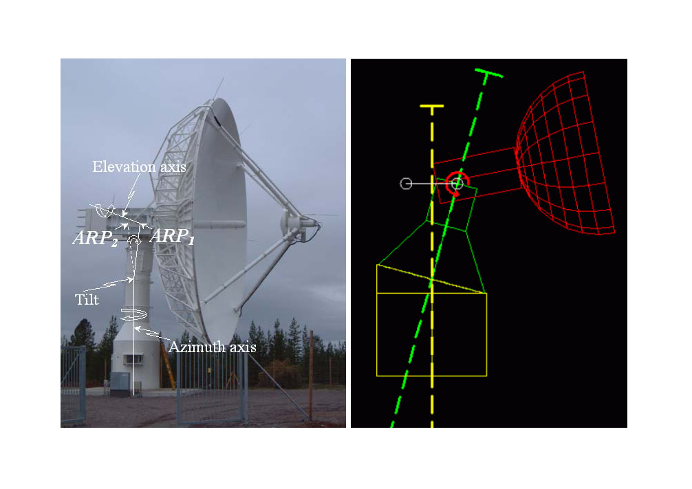
Figure 5: Antennae equipped with Tilt Mechanisms have more than only one ARP
Some other antennae that were measured are equipped with a constant 7o tilt, which can be rotated into any azimuth (tilt direction, 3rd axis). In order to determine the circle of the tilt cone, IM had in these cases to be made in three tilt positions per antenna.
“Exotic” Antennae
During the ESA TSD 2 campaign 2002 – 2005 also some antenna constructions were measured, at which azimuth and elevation axis do not cross. Figure 6 shows two examples. In such cases the ARP was defined as that point on the elevation axis that is located closest to the azimuth axis, i.e. the actual ARP position rotates on a horizontal circle, with the minimum distance between azimuth axis and elevation axis as radius, around the azimuth axis (and in some cases the ARP varies with the elevation too). For this type of antennae, the actual ARP position is a function of azimuth (and in some cases of elevation too) and must thus be defined through a formula.
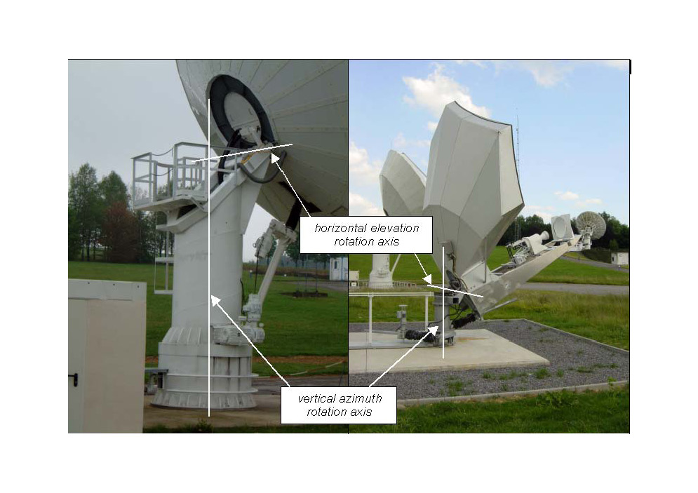
Figure 6: Two Examples of Antennae with Non-Crossing Azimuth and Elevation Axis
Inclusion of DSA-3 at MalargüE into the ESA TSD 2
In the course of 2012 the new ESA tracking site at Malargüe/Argentina was established ( http://www.esa.int/Our_Activities/Operations_Situational_Awareness/Malarguee_-_DSA_3 ), Figure 7. The Malargüe site hosts ESA’s third Deep Space Antenna (DSA-3) and ESOC’s Navigation Support Office has established a new IGS station named “MGUE” in Malargüe.
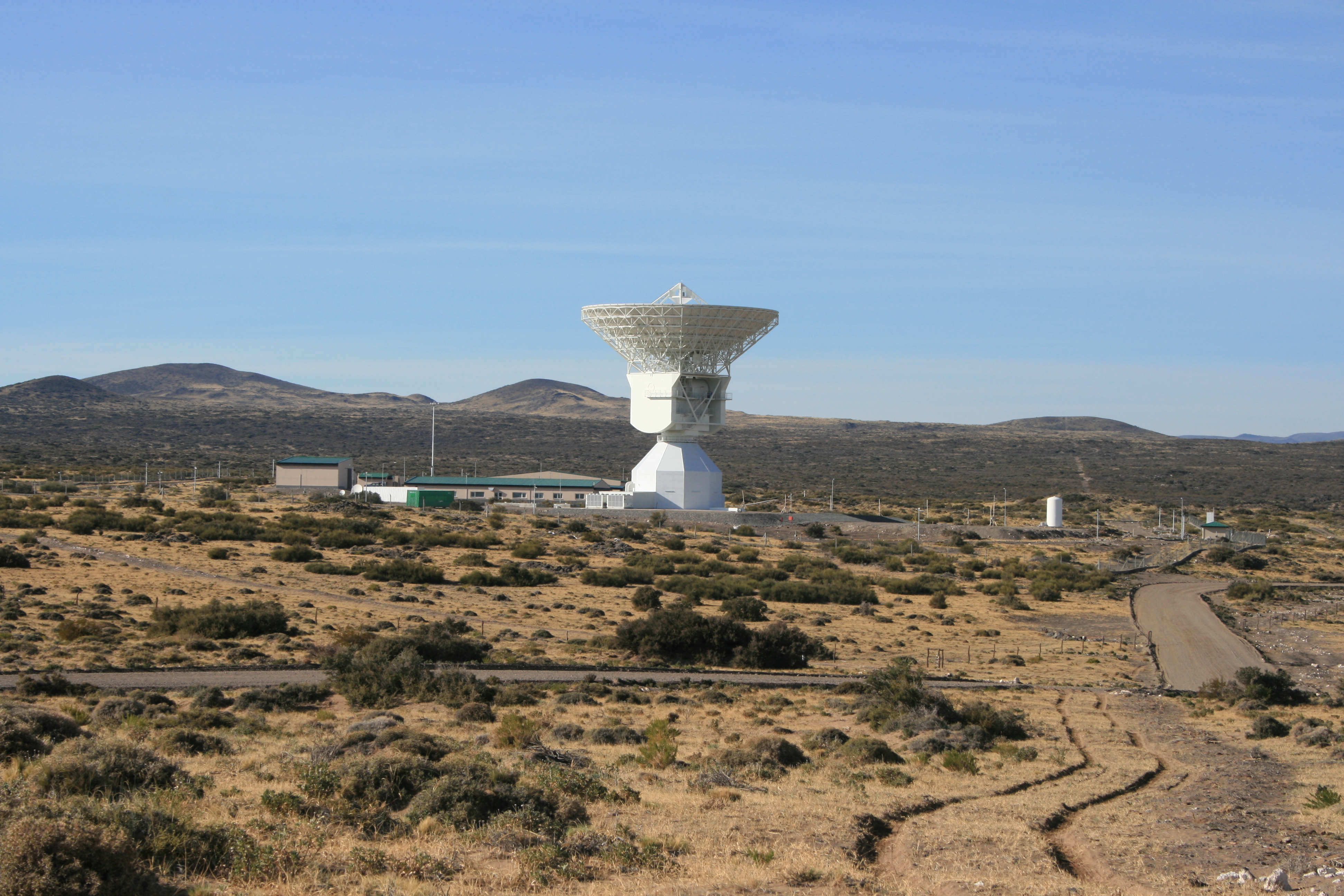
Figure 7: ESA’s new tracking site at Malargüe/Argentina
Figure 8 shows the geodetic network at the Malargüe site through which the connection of the ARP to the GNSS reference “MGUE”, and thus to the IRTF, was established.
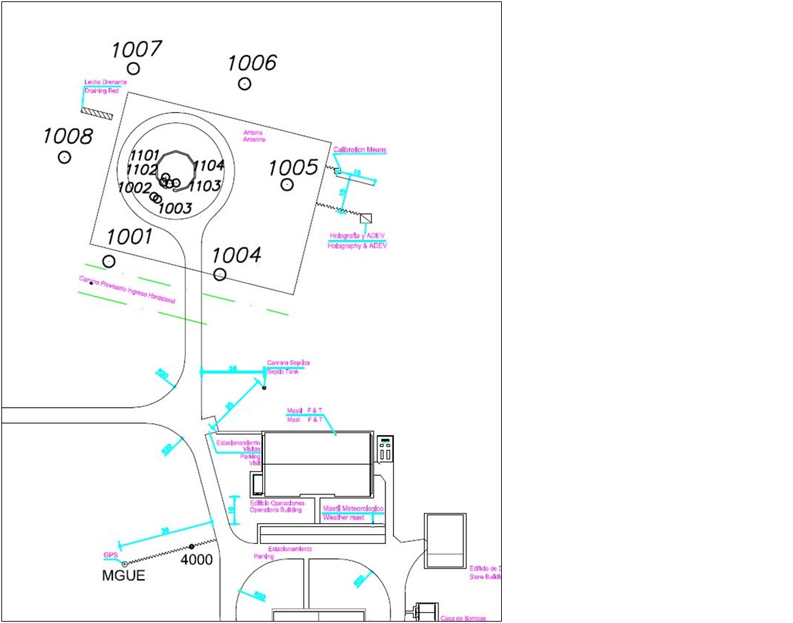
Figure 8: Sketch of geodetic network at Malargüe tracking site
The DSA-3 ARP was determined by all three methods described in Chapter 3: AT, IM, AB, of which the IM result was adopted as the final one. The IM ARP accuracy relative to the ITRF reference “MGUE” is ±2 mm in horizontal and vertical, and ±3 mm in 3D. The ARP coordinate differences between IM and AT are in the same order of 2-3 mm, the offsets between IM and AB are in the order of 1.5 cm. The absolute accuracy of the ARP depends on the ITRF accuracy of “MGUE”, which is currently about 6-7 mm in 3D. It is expected that this accuracy will enhance to a few (2-3) mm level in the course of the long term processing at ESOC/Navigation Support Office and within IGS. Figure 9 illustrates of the IM ARP measurements.
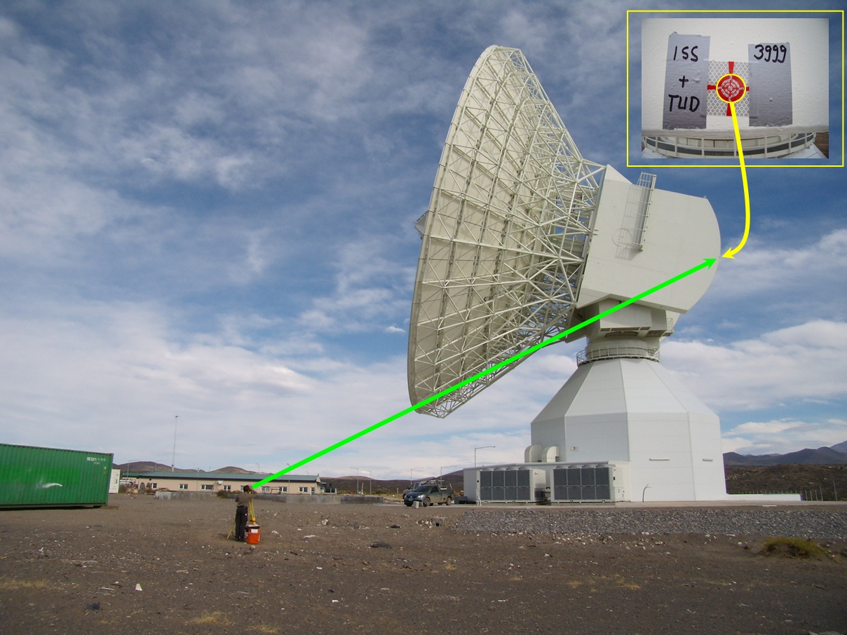
Figure 9: ARP measurements at DSA-3, Malargüe
Short Sumary of results / contents of the ESA TSD 2
Primary goal of the ESA TSD 2 is to serve as a database of the antennae and geodetic networks of the various tracking sites where satellite tracking antennae are operated by or in commission for ESA. The site directory is organized according to the following demands:
-
Electronic form
-
Coordinates in ITRF 2000 until 2012 upgrade, in ITRF 2008 since 2012 upgrade
-
High accuracy of ARPs
-
Complete documentation
-
Easy maintenance
The required accuracy stated for the ESA TSD 2 is ± 3 mm horizontal and ± 6 mm vertical accuracy of PCN points relative to the ITRF reference point. To obtain the global accuracy within ITRF, the reference point's accuracy has to be added. ARPs are derived with accuracies only slightly reduced compared to those of the PCN points in case of application of AT or IM method for their determination. Finally, the achieved ARP accuracy ranged, depending on antenna type, from several mm to 3 cm in a few cases for “exotic” antennae. Detailed tables, listing the achieved accuracies for different antennae, are given in Refs. [1] & [2].
The contents of the ESA TSD 2 are organized in a subdirectory structure, one per site: The main and summarizing document provides general information and overview on site, location, site map, geodetic network and antennae, sketches, photos, structure and contents of subdirectory. Detailed information is organized in two sub-subdirectories, one for the antennae (antenna, measurements and method of ARP determination, tilts, eccentricities, coordinates of ARP(s), etc., in addition photos and sketches or scans of available construction blueprints) and one for the on site geodetic network (per PCN point including the ITRF reference point: coordinates, marker, photos, etc., serves as database for future survey works).
Conclusions
For high-accuracy satellite orbit determination, precise knowledge of the geocentric coordinates of the Antenna Reference Point (ARP) is essential. The ESA TSD 2 project was initiated in 2002, providing a comprehensive catalogue of information about the antennae used by ESA. Apart from precise geocentric ARP coordinates in ITRF 2000, additional information about antennae construction and mechanics was made available, together with general information about the different tracking sites. In 2012 the ESA TSD 2 was extended for the new built DSA-3 in Malargüe/Argentina. At the same time the whole ESA TSD 2 was converted from ITRF 2000 (Ref. [3]) to ITRF 2008 ( http://itrf.ensg.ign.fr/ITRF_solutions/2008/ITRF2008.php ).
The ARP is defined geometrically as the intersection between azimuth and elevation axis (in the case of non-crossing, as the closest point between these axes). The point to which a tracking antenna's measurements (especially distance measurements) actually refer will in general be a different point, which might be denoted here as Electronic Measurement Point (EMP). To find the geometric relation between ARP and EMP is a matter of calibration. This geometric relation might depend on the antenna's elevation or be controlled by some kind of instrumentation, thus making the EMP's distance from ARP variable. Clarification of this issue is again a matter of calibration. This ARP-EMP relation has to be modelled and applied when evaluating the antenna’s measurements. Thus, as an enhancement of the antenna description part of the ESA TSD 2, the inclusion of a description of the ARP-EMP relation, calibration results and a proper mathematical model for applications would be desirable.
The last antenna so far measured and included into the ESA TSD 2 was ESA’s third Deep Space Antenna (DSA-3) in Malargüe/Argentina in 2012. Further extensions of the ESA TSD 2 for new antennae/stations in future are possible.
REFERENCES
[1] Feltens, J., J. Dow, M. Becker, S. Leinen, K. Sauermann (2005): “The ESA Tracking Site Directory Version II”, in Proceedings of the 28th ESA Antenna Workshop on Space Antenna Systems and Technologies, ESA/ESTEC, Noordwijk, The Netherlands, May 31 – June 3, 2005.
[2] Leinen, S., M. Becker, J. Dow, J. Feltens, and K. Sauermann (2006): “Geodetic Determination of Radio Telescope Antenna Reference Point and Rotation Axis Parameters”, Journal of Surveying and Engineering (JoSE), DOI: 10.1061/(ASCE)0733-9453(2007)133:2(41).
[3] Boucher C., Altamimi Z., Sillard P. and Feissel-Vernier M. (2004): “The ITRF 2000“, IERS Technical Note No. 31, Verlag des Bundesamts für Kartographie und Geodäsie Frankfurt am Main, 289 pp., 2004.